Radio Telescope Circuit Diagram
A radio telescope Telescope astronomy observation astronomical Pcb rf layout critique: input on my radio-telescope pcb
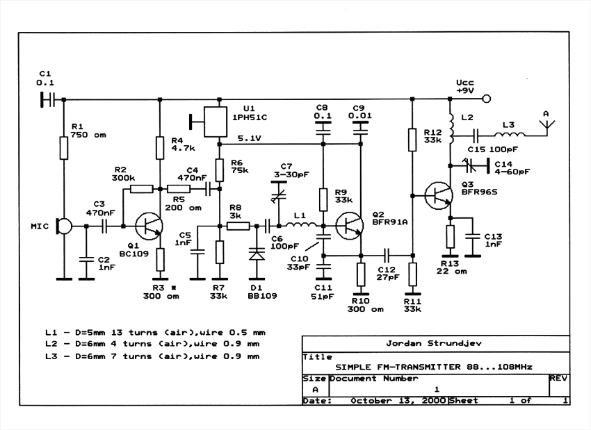
oscillator - Create a simple radio transmitter - Electrical Engineering
Telescope radio azimuth receiver dish inchbyinch support The schematic view of the refractive telescope system, from left to Radio telescope circuit diagram
Usb fm transmitter circuit, 60% off
What does fm transmitter do?Fm transmitter circuit diagram with explanation Block diagram of a radio telescope based on the receiver ral10. theThe schematic view of the refractive telescope system, from left.
Digital radio astronomy: radio astronomy station. part 2.10 simple fm transmitter circuits explained Radio telescope diagram digital astronomy raspberry pi sdr tvSimple am radio schematic diagram.

Schematic transmitter circuitlab
Transmitter fm circuit frequency miniature basic circuits do radio diagram calculate signal carrier antenna using microphone electrical electronics tune build500m fm 송신기 회로-전자-fmuser fm/tv 방송 원스톱 공급자 Radio frequency telescope prototypeRadio telescope students everyday affordable develop block diagram setup mandal pranshu et credit al choose board.
The astronomy and physics club to raise money for radio telescopeRadio power Spy circuit transmitter electronic diagram bug circuits make homemade fm build simple kits wireless projects explainedRadio telescope.

Fm modulator circuit
Build a radio telescope3 radio telescopes and radiometers‣ essential radio astronomy Radio telescope imageRadio fig telescope interferometer switching phase block diagram.
Radio frequency telescope prototypeHow do i calculate the frequency of an fm transmitter circuit Vlf receivers for sidsMaking a radio telescope.

Telescope noise amplifier lna
(pdf) low noise amplifier design for radio telescope systemRadio amateur Students develop an affordable everyday radio telescopeTelescope radio diagram making post receiver.
Fm transmitter circuits diagram schematicsSchematic diagram of the electronics used for a single telescope Telescope astronomy functions hardy operates tonyTransmitter rf mhz transmisor 100mhz schematics watt 500mhz 108mhz varicap.

100 watt fm transmitter circuit diagram
Fm radio transmitter circuitFm radio transmitter circuit diagram Pcb rf input telescope critique layout radio stackupElectronic assembly: remote radio telescope to 27mhz.
.


