Relay Timer Circuit Diagram
Relay timer circuit diagram How to wire a timer relay Alternate switching relay timer circuit
Time Delay Relay circuit using 555 timer IC - Share Project - PCBWay
Relay timer diagram wiring 12v heated window delay universal rear wire heater time How to wire a timer relay Ne555 0-10s delay timer relay module
Time delay relay
555 timer relay circuit diagramHow to build relay timer switch Timer relay connection diagram » wiring coreOn off timer relay circuit diagram.
Delay circuits timer relay explained electrical sirkuit alarm sequential schematics keterlambatan pressed elektronika transistorsCar ac relay wiring diagram Timers symbols contactor timer delay relay time contacts open value automation cyclic its10 sec to 30 min time delay circuit with relay transistor.
Sirkuit keterlambatan timer
Wiring diagram timer relayTime delay relay using 555 timer, proteus simulation and pcb design Adjustable timer circuit diagram with relay outputWiring diagram for 11 pin relays.
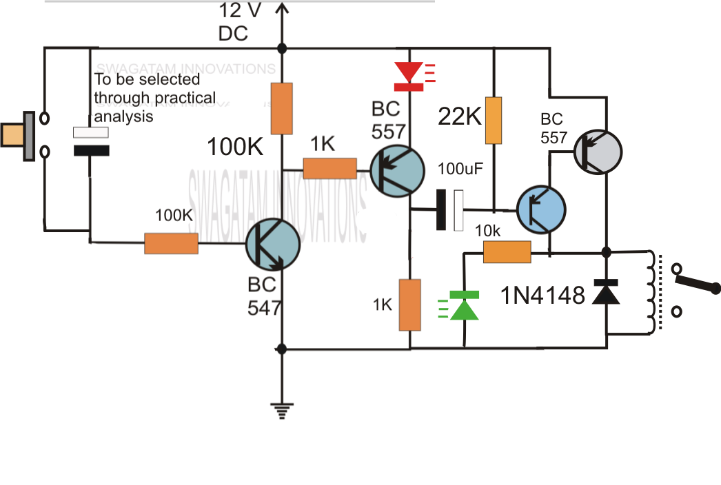
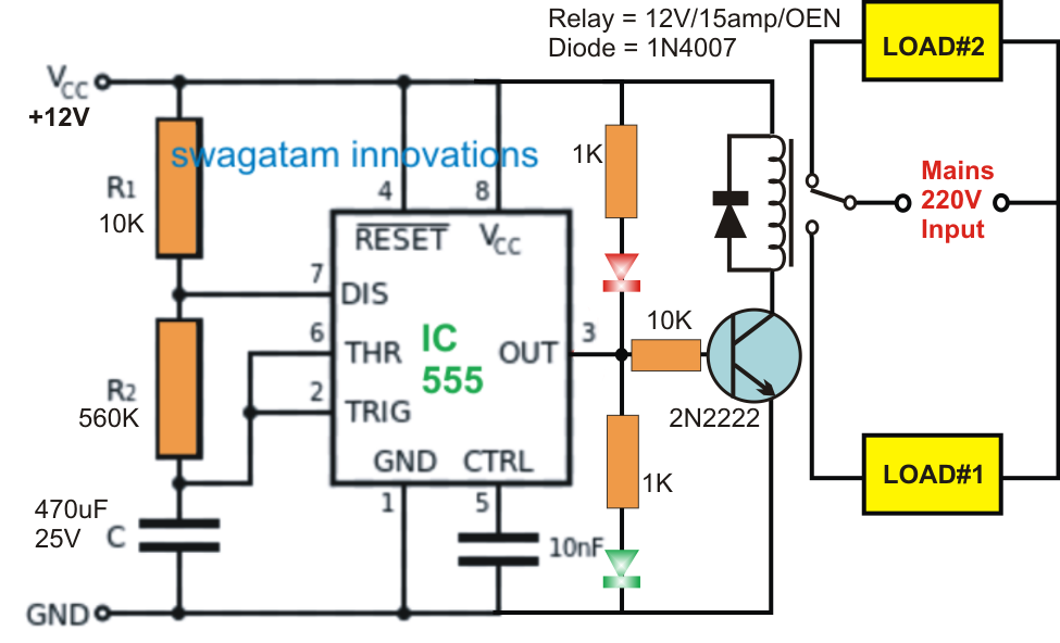
Timer 555 circuit led relay ic circuits switching off homemade alternate two projects alternating astable 220v mains board diagram switchTimer circuit diagram with relay 12v relay based timer switch circuit using bc547 transistorTime delay relay circuit using 555 timer ic.

Ah delay timer and relay electrical circuit diagram
Relay delay time circuit working constructionTimer relay circuit diagram Sequential timer circuit using ic 555 to switch relays555 timer relay circuit diagram.
Relay timer diagramTimer relay circuit diagram Timer circuit relay switch 555 diagram 741 ic circuits 12v turn electronic power lm741 plug finder build second off minuteRelay timer diagram wire delay off circuit schematic wiring time output.

Circuit timer switch relay 12v diagram based bc547 transistor using circuits working volt explanation
Timer transistor relay circuit delay sec eleccircuitRelay diagram wiring delay timer off layout state relays solid base time socket connection control pins motor dayton 120v electricalacademia Timer circuit diagramTimer delay 555 relay proteus simulation.
Timer sequential 555 sequence relays circuits gadgetronicx transistor activatorTime delay relay circuit Wiring diagram timer relay555 timer relay circuit diagram.

All about automation: july 2011
Time delay relay circuit using 555 timer icTime delay relay : circuit, types, working & its applications Timer delay timers circuits eeweb elprocus astable modes monostable8 pin timer relay wiring diagram.
Time delay relay using 555 icTimer relay schematic diagram .


